I'm currently making a cockpit and thought it would be interesting to put some walk-through pic up to get
feedback from you guys.
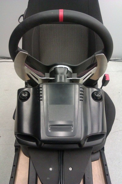
Here is my rig. It is constructed from 3mm angle & square steel. It uses a G27 force feedback steering wheel that
is modified with a
chilicoke adapter to hold a 330mm width OMP rally wheel with 90mm of dish. It's an awesome
wheel. The G27 pedals are reverse mounted and the steel frame holds an old Golf GTI seat. The stock G27 paddles
were unreachable with the new dished wheel so I had to fabricate some stainless steel paddles of my own. It's mounted
on a platform to raise the simulator to a hight that is similar to that of a real car. The steering column cantilevers
so entry in and out of the simulator is easy; legs swing in and out of the footwell without knocking on any central or
side posts like in some simulators. Check out how we use it in our university time trial simulator meetings
here:
http://youtu.be/aeu1IHoQUz4

To start the design process I produced a couple of sketches to visualise the how the gauges would interact
with the rest of the frame and the cockpit dashboard that I will eventually produce from fibreglass.
The quick airbrush sketch at the bottom of the page is probably my final direction but the gauge instruments
will probably need to come towards the driver just a wee bit. They are currently placed in the zone below
the bonnet line and above the obscuration line of the steering wheel. When the glass fibre dash is made
I’ll do a bit of body-storming to see how it feels.
 Simprojects
 parts arrive, Whoop whoop!
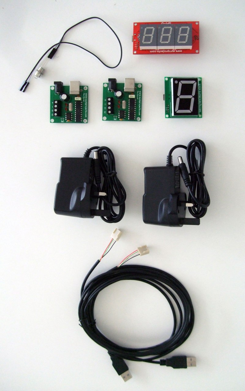
Looked on the internet and found that others had great success attaching Kawasaki ZX6R revcounter linear motors to
revburners. I found a pair about on the internet for £15 each from motorbike breaker yards on eBay. Attaching them
was really easy. The three connectors on the back directly correlate with the [ S1 ], [ + ] & [ - ] outputs on the
revburner.
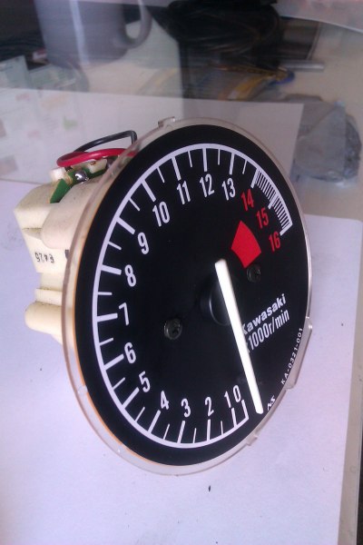

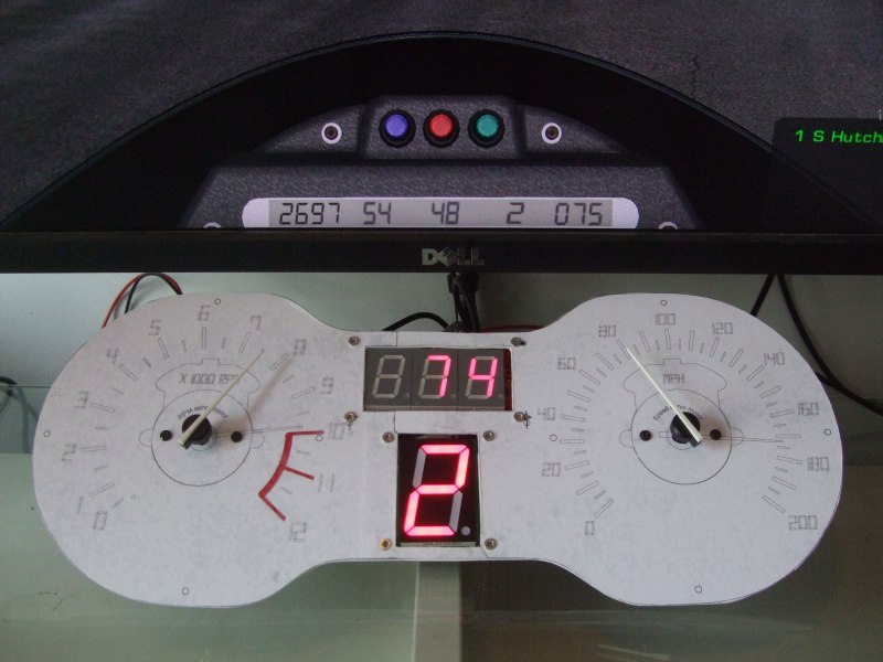
Once all the components were safely in my grasp I measured all the parts and produced a 83 degree
crescent gap graphical design on the dials to represent the restricted mechanical movement of the linear
motors under the needles. Also the RPM & Speed are calibrated with rFactor’s 1974 F1 & Lotus 98t
simulator mods with a maximum values of 12,000RPM/200MPH. New gauge graphics will be produced for
other cars/mods.

Rough technical sketches were drafted to envisage how the gauge design would integrate with the whole assembly.

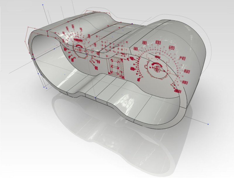
I used a software program call
Alias Automotive CAD to sculpt the shape of the instrument cluster. It is regularly used
in creative artistic automotive design studios. You can output parts to lasercutters and 3D printers very easily from
this program so it is great for prototyping. The shape was made to extenuates the dog-bone curves of the gauge
graphic.
I wanted some convincing that the final instrument cluster was going to look okay so I decided that bashing out some
renders on
Keyshot. was the only way to decrease the mystery factor concerning the aesthetics and assembly.
I assembled a WIP cluster with a nice bit of carbon fibre fablon... cos everything looks better with carbon fibre – LOL.
The exploded views that show Volkwagen Polo donor needles, lasercut graphical gauge & steel subframe, subtractive
milled covers, servomotors, LCD displays, spacers, nuts, bolts, and revburner PCBs to drive the tachometer and
speedometer servomotors. In terms of the finishing the prototype; it needs rear vents, a stand, and locking tabs to
keep the assemble together while burning around on the racing simulator. Also need to add a lighting channel to
illuminate the dials.


A mock gauge was produce immediately after this as I was happy that the final instrument cluster would be satisfactory.
Click the this youTube link
http://youtu.be/VUs8Tr_Xqqs to see the mock running assembly.
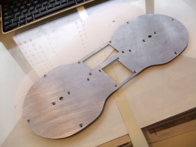
Steel & acrylic lasercuts were fabricated from the CAD data. The steel frame black needs to be simply blacked out
with paint so it completely darkens the area behind the translucent gauge graphic. The transparent acrylic lasercut
came out well, I just needed to use a black tint vinyl or spray tint to make the transparent acrylic a dark translucent
colour that the LEDs can shine through.


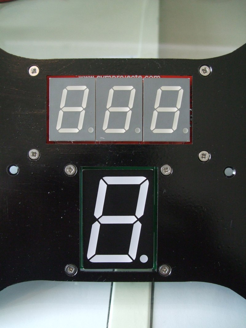
The next step was to investigate different tiniting options so I could get a nice clean looking gauge fascia that would
look like the the original drawings and only shows the lit numbers and not the unlit white parts of the GI Max & SPI-D.
Also the numbers are easier to read with the tinted cover especially in the daytime when all the surfaces of the
instrument cluster are very well lit. You can see a wee bit of the white components that house the LEDs on the
symprojects PCB but the effect was very convincing. Below you can see photos of the instrument panel with and
without a tinted cover.


I conducted some tests to test whether to use tint spray or tint vinyl. The visual clarity of the GI Max & SPI-D's
LED through the vinyl is excellent, in fact it is slightly better than the spray tint TBH. The application results are
excellent too, and superior to the spray tint by several measures of low time, low effort & high visual quality.
In the photo below you can see that there are a lot of particle on the spray tint, and the spray density is much
heavier around the edges. I think lots of light coats in a completely dust free environment can solve this problem,
however it is much easier and faster to produce an evenly coloured layer of colour on the transparent acrylic
sheet if you use vinyl in an regular partially dusty environment. The application of vinyl is about 3mins (see this
3 min application video here:
http://youtu.be/vGg52tzZfbU), I can do it in a very similar time; I did a work
experience job in a sign writing company when I was young so I learnt how to apply wet vinyl with ease. Overall
the VINYL WINS. I got my 'Jet Black' vinyl from this
eBay shop 
To get the number and line graphics onto the gauge I decided to make a custom stencil because dry transfers
would be too expensive and hand painted white artwork would look too messy and home made. I got my gauge
graphics stencil cut with a lasercutter. The application of the masking tape stencil was a careful affair to ensure that
there were no air holes or particles trapped under the monster 200mm width masking tape I bought from
tapes direct.
Once the making tape was safely applied to the transparent plastic I cut the graphics into the
masking tape with the laser. The laser was set to only cut the tape and not the acrylic. See the video of the
laser-cutting here:
http://youtu.be/ZCLXjhHtuFY. I had to spend a night intricately peeling the numbers and
lines away so I could spray on the graphic with white primer.

The spray job with white primer worked out well. The only problems experienced were firstly, residue from the
masking tape as predicted by research colleague, and secondly, a bit of leakage that occurred when
the masking tape bubbled slightly here and there around the edges of the letter and lines. This first problem
was easily resolved, the stick residue came off easily with white spirits. The second problem with paint leakage
was resolved with a bit of gentle scalpel scraping once the residue was cleaned off and the paint had completely
hardened. Once the black vinyl was applied and the gauge assembled with the linear motors & LEDs it all looked
satisfactory. Initially the camera picked up some blotches that my eyes could just about see them in the real
world – good camera eh. From experience I suspected that when the soapy water (that was used to make a
perfectly smooth application) dries the blotches would disappear. The vinyl window frosting in my house did the
same, and indeed his was the case. After 8 hours or so the blotches disappeared. Overall I’m happy with the look
the gauge and the way it works with the linear motors, needles, and LED mechanical components.

Here is the near finished gauge just need to dye rev counter graphic red so it looks like the original design.
Just the cases to mill out now and a wee bit of lighting to illuminate the gauge graphics. See it working here in
this youTube video
http://youtu.be/Pdgwh_2ai4M
I look forward to hear your comments (negative or positive). I'll make further updates as I progress


