


This is a newer version of the JC-LED controller.
Instructions for the previous version are available in this page.
Characteristics
The JC-LED controller is able to drive a big number of 7-segment displays. Each 7-segment display can be replaced by a group of 8 leds.
7-segment displays and leds can be mixed together, with the same controller.
- The controller can drive up to 64 7-segment displays. The displays can be used to build a gear position indicator, a speedometer or to display the current lap time. Any display size or color are compatible but the displays must be common cathode type (not common anode). Common cathode means that the eight leds inside the display share the negative pin.
- Each of the 64 7-segment displays can be replaced with a group of eight LEDs. These leds can used to build a shift array display or as a hand brake indicator, water temperature warning or oil pressure warning lights, etc... If all 64 7-segment displays are replaced with a group of eight leds each, 512 leds can be connected in total.
Display banks

In the pictures of the JC-LED controller you can see there are 4 terminal blocks used to connect displays and leds. Each terminal block is called BANK, in these instructions and in the software (SimDash).
There are BANK 1, BANK 2, BANK 3, BANK 4.
To each BANK you can connect 16 7-segment displays (each 7-segment display can be replaced by 8 leds).
All the 16 7-segment displays connected to one bank share the same S1...S8 connections. These connections are used for the anode pins of the displays.
The common cathode pin of each display is connected to one of the D1...D16 connections of the bank.
Connection D1...D16 are not shared among displays. Each display is connected to its own D connection.
Connecting 7-segment displays
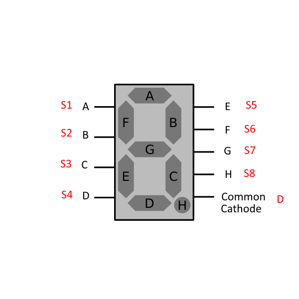
Display that are connected to the JC-LED controller are of type common cathode (instead of common anode). Common cathode means that the eight leds composing the display share the negative pin. Looking at the picture above, the pins A...H of the display connect to pins S1...S8 of the JC-LED. The common cathode pin instead connects to one of the D1...D16 pins of the JC-LED (only to one of them).
Same thing if the 7-segment display is a multiple display, like the one below:
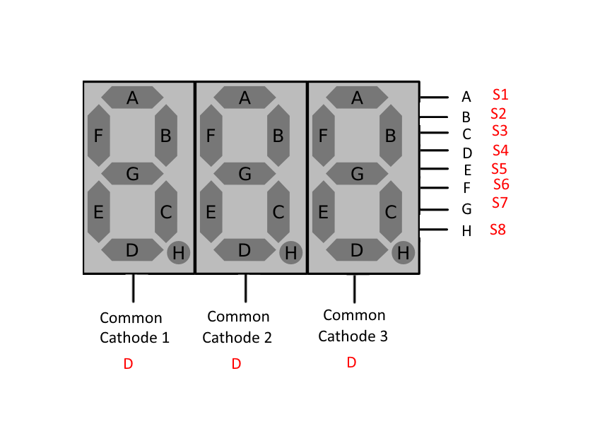
Pins A...H of the display are connected to pins S1...S8 of one of the banks of the JC-LED controller, but now there are three cathode pins on the display (one for each digit) that must be connected to three separate D1...D16 pins of the same bank.
Connecting LEDs
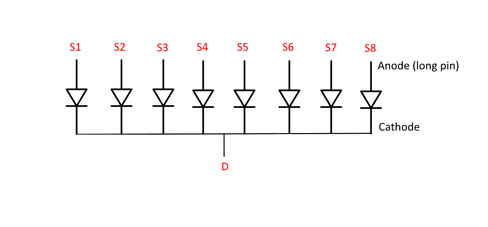
Each 7-segment display can be replaced by a group of leds. they are organised like in the picture above: their positive pins are connected to pins S1...S8 of one of the bank of the JC-LED controller. Their negative pins (cathodes) are linked together and connected to ONE of the D1...D16 pins (only to one) of the same BANK.
The Configuration screen
The picture below is the JC-LED configuration screen.

- 1 shows the configured Display Groups. A display group contains the information about how to display a certain piece of data, which unit to convert the data to, how many digits to display, the position of the decimal separator and more. For example, if we were displaying the water temperature, we would have to choose how many figures to display before and after the decimal point, if the temperature is displayed in Fahrenheit or Celsius degrees and whether we want the displays to blink in certain situations.
- 2 are the configuration settings for a specific display. In the picture above display 1 is displaying the first digit of the display group "Gear position".
- 3 is a TEST button. If you click the button the corresponding display or group of leds will switch on. This function is useful when you want to check that a display of group of leds is connected to the JC-LED correctly.
- 4 this group of buttons is for creating, editing and deleting display groups and for importing and exporting the JC-LED settings.

The Brightness section (above) of the configuration screen allows you to adjust the brightness of the displays and leds connected to the JC-LED. There are 8 positions available.
The brightness of each BANK of leds can be individually adjusted.
Configuration Example 1
In this example I am going to to configure four displays to show the water temperature in Celsius degrees. I want the displays to blink when the temperature is above 90 degrees.
- First thing to do is to open the JC-LED configuration screen and click the New... button. A new dialog will pop up and you will be able to define the settings for the water temperature read-out.

- Referring to the picture below, put a name in the textbox highlighted by arrow 1. It can be any text but it is easier if it describes the data value being displayed. Click the button highlighted by arrow 2 to select the data to display (water temperature in our case).

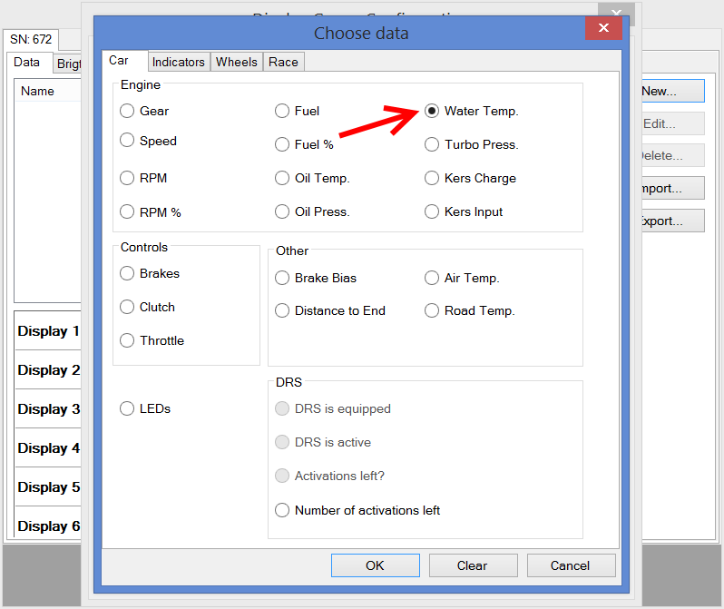
- The next screen will show more settings that need to be configured. Referring to the picture below:
- (1) is the unit used to display the water temperature.
- (2) highlights two drop down lists. The first one sets the number of figures before the decimal point, the other one is the number of figures after. In our case we want three figures before the decimal point and one after. So the displayed water temperature will be something like 123.4
- (3) these two checkboxes sets whether the decimal point should be displayed (Yes, in our case) and whether the displayed value should always have four figures, even if the temperature is below 100 degrees (for example 9.5 would be displayed as 009.5).
- (4) the controls in the blinking section set if and when the displays should blink. We set the displays to blink at medium speed when the temperature is above 90 degrees.

The settings displayed in this screen can be a bit different in some cases, for example if you choose to display the gear position or the lap time, but in any case they should be intuitive to use and easy to understand.
- Now that we have configured the water temperature read-out and in particular we have configured it to use four displays (three before and one after the decimal point) we have to assign each of the four digits of the water temperature value to some of the 7-segment displays that are connected to the JC-LED controller. In the picture below digit n.4 (the leftmost digit of the water temperature value) is assigned to display n.1n BANK 1. Digit n.1 (the rightmost digit of the water temperature value, that is the digit after the decimal point) is connected to display n.4, BANK 1.

Configuration Example 2
In this configuration example I am going to use some LEDs to display the shift light and the hand brake warning lights. I am going to replace Display n.1 of BANK 1 with 8 LEDs.
The 8 LEDs have their positive pins (the longer pins) connected to pins S1...S8 of the JC-LED controller. The negative pins are connected together to pin D1 of the JC-LED (because the 8 LEDs are replacing display n.1).
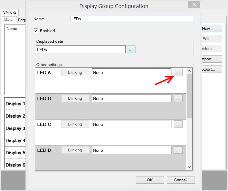
- Open the JC-LED configuration screen and click the New... button. The dialog shown below will appear. Put a name in the Name textbox and click the button highlighted by the red arrow 2.

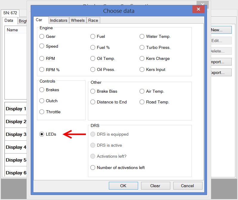
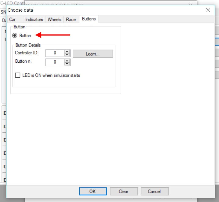
- In the Choose Data dialog select LEDs and click the OK button.
- Now the configuration screen should be like in the picture below. Now you can configure one LED as the shift light and one as the hand brake warning. I decided to use LED A and LED B.
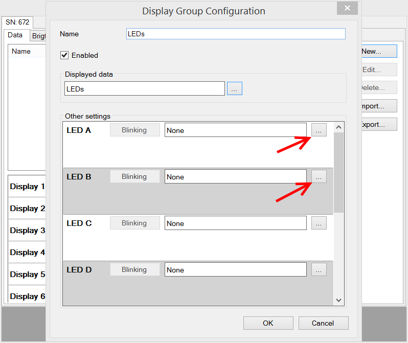
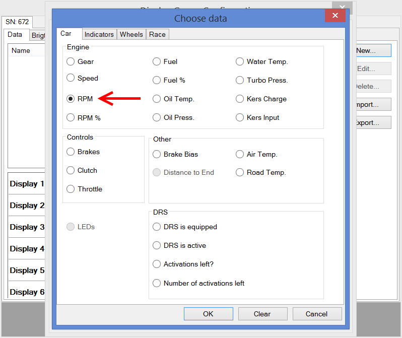
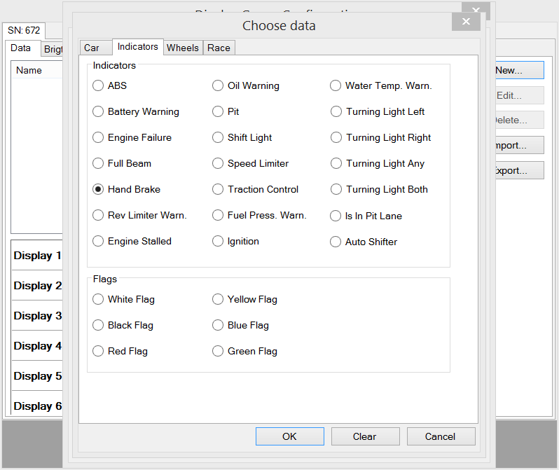
- Click the two buttons highlighted in the picture above and choose what data LED A and LED B will be associated with. Choose RPM for LED A and Hand Brake for LED B.
- Now complete the configuration of LED A setting the RPM value at which the LED should be switched ON. You can also set the blinking conditions and speed if you wish. The configuration screen should be like in the picture below:
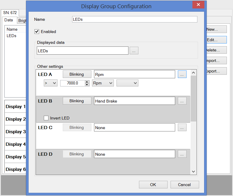
- The last step is to assign the LEDs we have just configured to Display 1.

Configuration Example 3
In this configuration example one LED will be turned ON and OFF every time a push button is pressed. The LED is not associated to any telemetry data but it just responds to button presses. I am going to replace Display n.1, BANK 1 with 8 LEDs. The first of these 8 leds will respond to the push button connected to the JC-LED (only version 1) or Pro-Race or JC32 or JC24 controllers.
The 8 LEDs have their positive pins (the longer pins) connected to pins S1...S8 of BANK 1 of the JC-LED controller. The negative pins are connected together to pin D1 of the same BANK (because the 8 LEDs are replacing display n.1).
- Open the JC-LED configuration screen and click the New... button. The dialog shown below will appear. Put a name in the Name textbox and click the button highlighted by the red arrow 2.
- In the Choose Data dialog select LEDs and click the OK button.
- Now the configuration screen should be like in the picture below. Now you can associate the first LED to one of the JC-LED, Pro-Race, JC32 or JC24 buttons .
- Click the button highlighted in the picture above and choose which button will be associated to the LED.
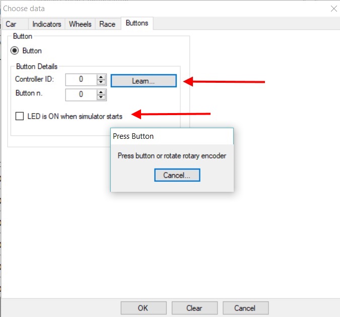
- You can also choose the state of the LED when the simulator starts. If it is going to be switched ON or OFF at the beginning.
Custom firmware
If you would like to integrate the JC-LED controller in your products, like button boxes, wheels... a custom version of the firmware that reports the name of your company and of your product is available. This is a free service but a minimum quantity order might be required.
| 3DModelAttributeGroup | |
| 3DModel | https://raw.githubusercontent.com/ccesaretto2/3DObjects/refs/heads/main/JC-LED.stl |
JC-LED
- Product Code: JC-LED
-
£37.00
Available Options
Related Products

0.36" Six digit display for JC-LED
A 9.2mm (0.36 in high) RED six digit seven segment display. Ideal for displaying lap time.The displa..
£6.95

0.56" display for JC-LED
This is a 14.2mm (0.56in high) seven segment display RED display for the JC-LED controller.The displ..
£5.95

0.56" Three digit display for JC-LED
A range of 14.2mm (0.56in high) three digit seven segment displays available in red, green, and blue..
£5.95

1.5" display for JC-LED
A 38 mm (1.5in high) RED seven segment display.The display is already soldered on a PCB with a pin h..
£7.45

8 LEDs display for JC-LED
LEDs can be any combination of red, green, blue and yellow. Please send an email to contact@symproje..
£5.95

20 pin dual female splittable jumper wire - 300mm
This is a splittable, super flexible 20 pin dual female jumper wire.It can be used to connect the LE..
£3.99

0.56" Two digits display for JC-LED
This two digits RED display is only compatible with the JC-LED controller, not the DLC-247.This two ..
£6.95