In fuel and temp gauges i'm talking about the signal because the own cluster send the signal to a variable resistor and returns to the cluster again.

I can't tell you the colour because i don't have the right connector.
But:
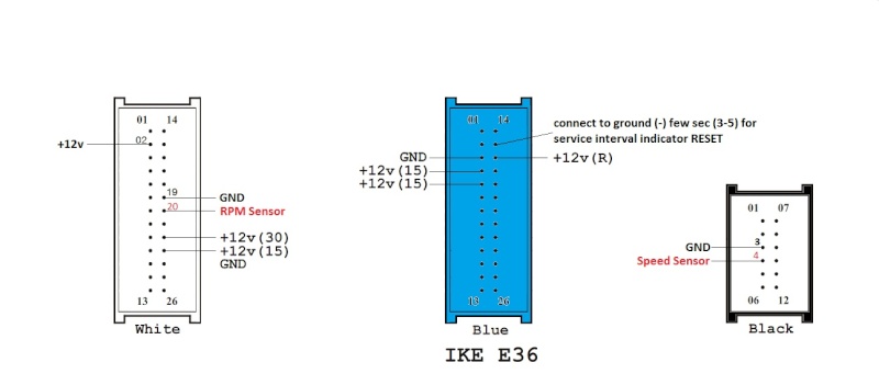
White Connector:
Pin 2: cluster light / dimmer
Pin 19: - to ground
Pin 20: RPM Sensor signal
Pin 22: +12v (30) permanent (hot all times)
Pin 23: +12v (15) use a switch to on/off (hot in run)
Pin 24: - to ground
Blue Connector:
Pin 3: - to ground
Pin 4: +12v (15) use a switch to on/off (hot in run)
Pin 5: +12v (15) use a switch to on/off (hot in run)
Pin 15: the same as the described (image)
Pin 16: +12v (R) use a switch to on/off (hot in run)
Black Connector:
Pin 3: - to ground
Pin 4 : Speed sensor signal
with some research i knew the +12v (30) needs always power, and now i'm trying to figure out the difference of the +12v (15) and +12v (R) but i think it varies depending on the position in the ignition.
IGN position:
0: off
1: acc
2: run
3: start
If i discover i post it ASAP.
Edit:
+12v (R) is position 1 (acc)
+12v (15) is position 2 and 3 (run & start)
So if am i right according the diagram with this you can test your cluster. (you need 2 switch's to do this, acc only for 1 switch, and run & start to the other)
+12v (30) permanent power
+12v (R) position 1 (acc)
+12v (15) position 2 and 3 (run & start)

Step 1. Press and hold the mileage reset button.
Step 2. Put key into ignition switch and turn position #1
Your LCD display will show something like this "tESt 01"
Step 3. Once "tESt 01" is shown, let go of reset button and the IC
(Instrument Cluster) will go through
some test cycles. Numbers will be shown and here's what they mean:
1st display: BMW PART NUMBER (6 digits)
2nd display: CODE NUMBER (5 digits) Internal Coding Plug #
3rd display: K NUMBER (4 digits)
4th display: CHASSIS NUMBER (5 digits) this is part of your VIN
5th display: SOFTWARE VERSION (3 digits)
6th display: REVISION INDEX (2 digits) Hardware #
After all 6 displays are finished, an analog gauge test will be performed.


