DLC-247 configuration
The DLC-247 (Displays and LEDs Controller 24 x 7 segments displays) is an USB controller able to drive up to 24 7-segment displays or up to 192 LEDs or a combination of displays and LEDs. In order to work with the DLC-247 controller, the displays must be common anode, which means the 8 LEDs that compose the display (one for each of the 7 segments and one for the decimal point) share the same positive pin, instead the negative pins are separate.
Below is a picture of the DLC-247 controller. Some components of interest are highlighted.
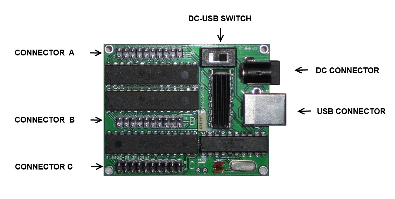
- The DC connector is used to connect the included 5V power supply to the DLC-247. The external power supply is not always required and in some situations the controller, displays and LEDs can be powered from the USB bus. Whether the power supply is required or not depends on the number of displays and LEDs being used and their brightness. The configuration screen of the DLC-247 in SimDash will give you indications on whether the power supply must be connected or not, based on the current configuration.
- The DC-USB SWITCH must be set to the DC position when the external power supply is used. It is set to the USB position when the controller, displays and LEDs are powered from the USB bus. This switch should be toggled when the USB cable is disconnected from the DLC-247.
- There is a set of three 20-pin connectors on board the DLC-247, marked with the letters A, B or C on the pcb. The pins of each connectors are numbered from 1 to 20.
- Pins 1…8 are connected to the cathodes (negative pins) of up to 4 displays or 32 LEDs or a combination of displays and LEDs. Because the 4 displays share these pins, the displays are multiplexed, which means that only one of the four displays is switched on at a given time. Each display is switched on and off there quickly (100 times every second) so for the human eyes they look like they were all on at the same time.
- Pin 9…16 work like pin 1…8: they are connected to the cathodes of 4 displays or 32 LEDs or a combination of displays and LEDs.
- Pin 17…20 must be connected to the anodes (positive pins) of the displays and LEDs. Each pin can connect to one or two displays. If the pin is connected to two displays, the cathode pins of the first display must be connected to pins 1…8 and the cathode pins of the second display must be connected to pins 9…16.
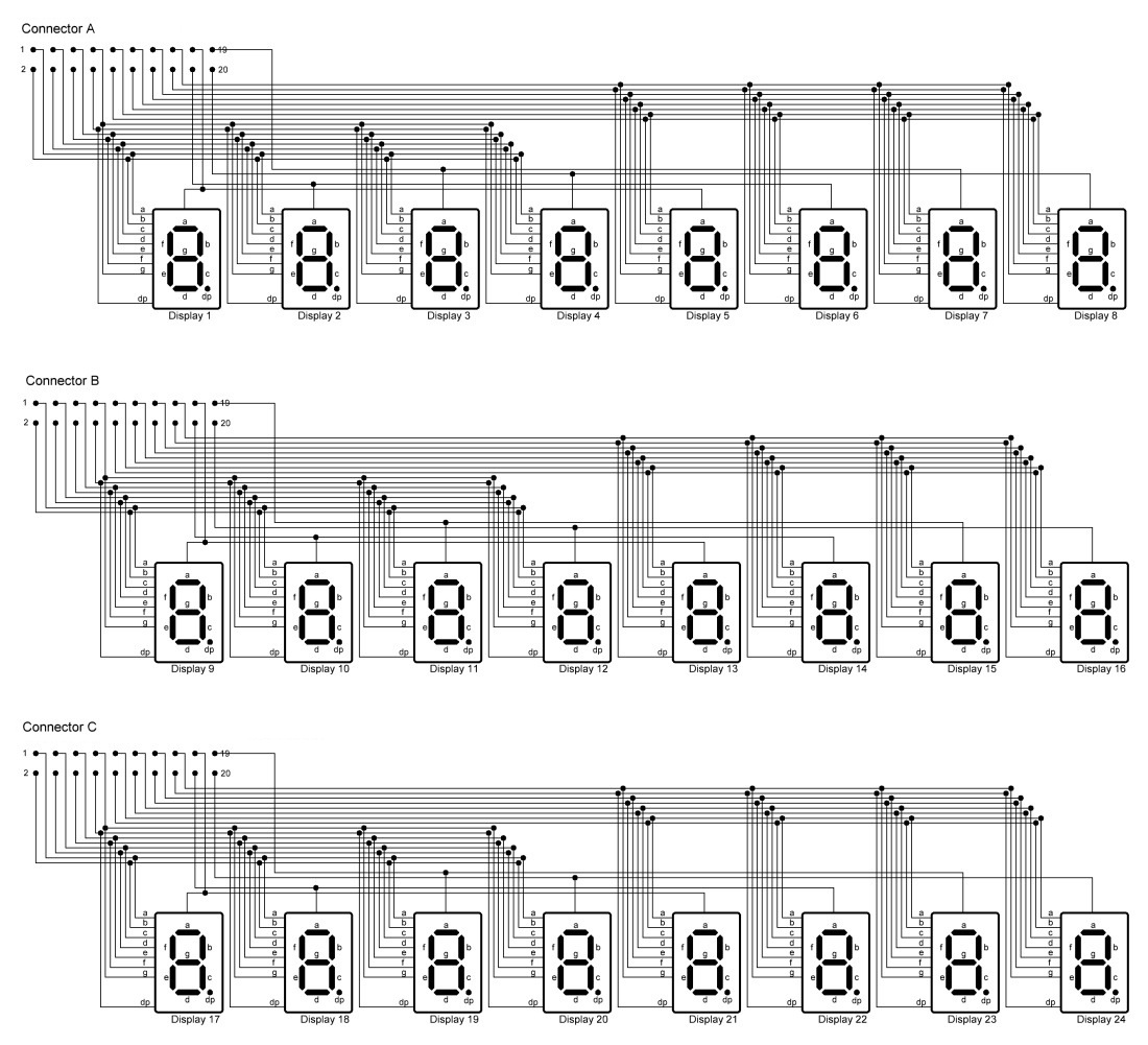
The picture below will help to understand better how displays and LEDs are connected to the pins of the DLC-247 controller. Based on what pins the display is connected to, the display will be identified by a number from 1 to 24. This identifier will be also used in the DLC-247’s configuration screen in SimDash.
Connecting LEDs
Each display can be replaced by a group of 8 LEDs. The 8 LEDs share the positive pin (anode) which is connected to one of the pins 17…20 of one of the three connectors. The 8 negative pins instead (cathodes) are connected to pin 1…8 or pin 9.16 of the same connector.
In the picture below Display 1 has been replaced with LEDs. The negative pins of the LEDs are connected to pin 1…8 and the positive is connected to pin 17. Each LED is identified by one letter from A to F or DP. These identifiers are also used in the configuration screen in SimDash.

From the picture you can see that pin 1 or 9 always connect to LED A or segment A of a display. Pin 2 or 10 always connect to LED B or segment B of a display and so on.
The Configuration screen
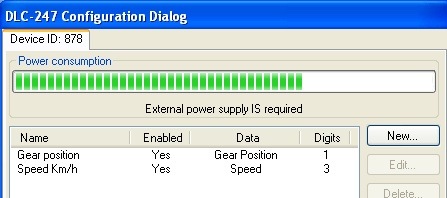
The picture below is the DLC-247’s configuration screen.
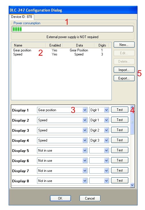
- 1 is the power consumption bar. It shows whether the external power supply is required, based on the number of displays and LEDs used and their brightness.
- 2 shows the configured Display Groups. A display group contains the information about how to display a certain data, what unit to convert the data to, how many figures to display, the number of decimal figures and more. For example, if we were displaying the water temperature, we would have to choose how many figures to display before and after the decimal point, if the temperature is displayed in Fahrenheit or Celsius degrees, the brightness of the display and whether we want the displays to blink in some situations.
- 3 are the configuration setting for a specific display. In the picture above display 1 is displaying the first (and only) digit of the display group “Gear position”.
- 4 is a TEST button. If you click the button the corresponding display or group of LEDs is turned on. This function is useful when you want to check that a display or group of LEDs is connected to the board correctly.
- 5: this set of buttons is for creating, editing and deleting display groups and for importing and exporting the DLC-247’s configuration.
Example 1
In this example I am going to configure four displays to show the water temperature in Celsius degree. I want the displays to blink when the temperature is above 90 °C.
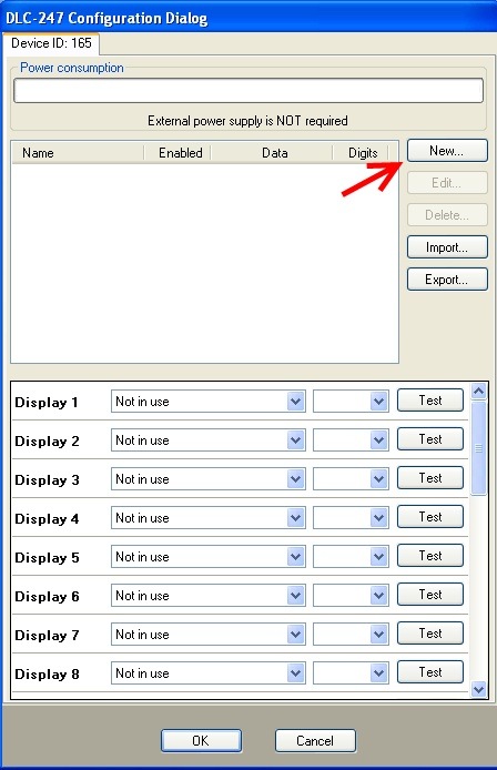
- First thing to do is to open the DLC-247 configuration screen and click the New… button. A new dialog will pop up where we can define the settings for the water temperature read-out.
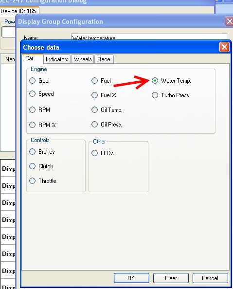
- Referring to the picture below, put a name in the textbox highlighted by arrow 1. It can be any text but it is easier if it describes the data value being displayed. Click the button highlighted by arrow 2 to select the data to display (water temperature in our case).

-
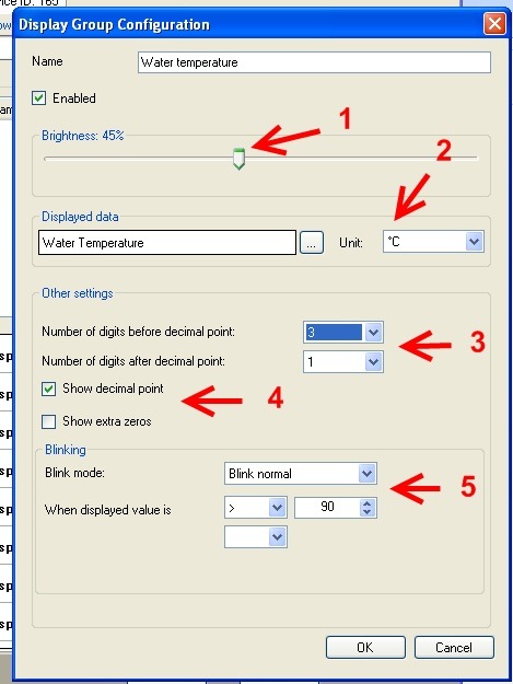
The Other Settings section will show more settings that need to be configured. Referring to the picture below:
- (1) is the brightness of the group of 4 displays.
- (2) is the unit used to display the water temperature.
- (3) highlights two drop down list. The first one sets the number of figures before the decimal point, the other one is the number of figures after. In out case we want 3 figures before the decimal point and one after. So the displayed water temperature will be something like 123.4
- (4): these two checkboxes sets whether the decimal point should be displayed (Yes, in out case) and whether the displayed value should always have four figures, even if the temperature is less than 100 (for example 9.5 would be displayed as 009.5).
- (5): the controls in the blinking section set if and when the displays should blink. We set the displays to blink at medium speed when the temperature is above 90°C.
The settings displayed in the Other Settings might be a bit different in some cases, for example if you choose to display the gear position or the lap time, but it should be easy to understand what they are used for.
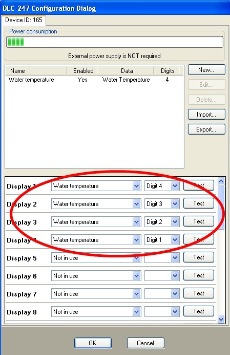
- Now that we have configured the water temperature read-out and in particular we have configured it to use four displays (three before and one after the decimal point) we have to assign each of the four digits of the water temperature value to any of the 7 segment displays that are connected to the DCL-247. In the picture below Digit n.4 (the leftmost digit of the water temperature value) is assign to display n.1. Digit n.1 (the rightmost digit of the water temperature value, that is the digit after the decimal point) is connect to display n.4.
Example 2
In this configuration example I am going to use some LEDs to display the shift light and the hand brake warning light. I am going to replace Display 1 with 8 LEDs, like in the picture below:
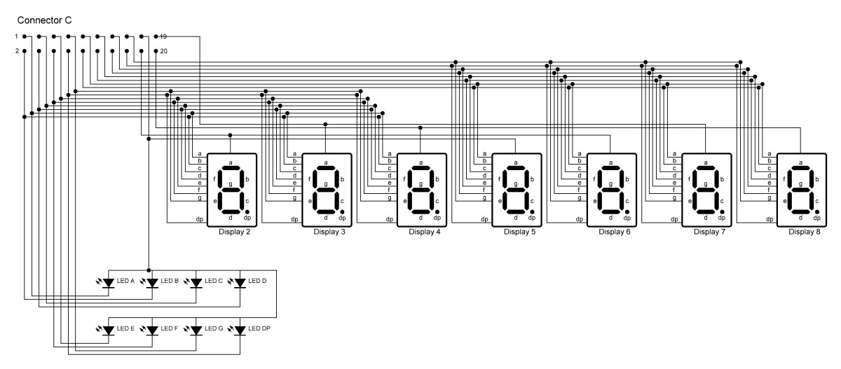
The 8 LEDs are connected to the pins of connector C that otherwise would have been used by Display 1.
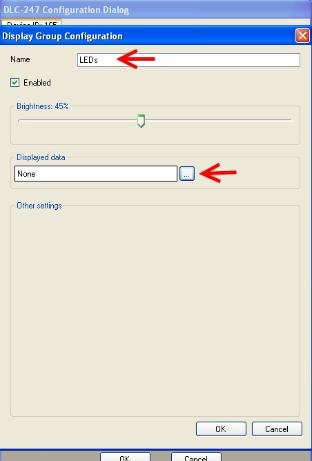
- Open the DLC-247 configuration screen and click the New… button. The dialog shown below will appear. Put a name in the Name textbox and click the button highlighted by the red arrow.
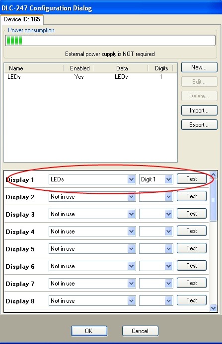
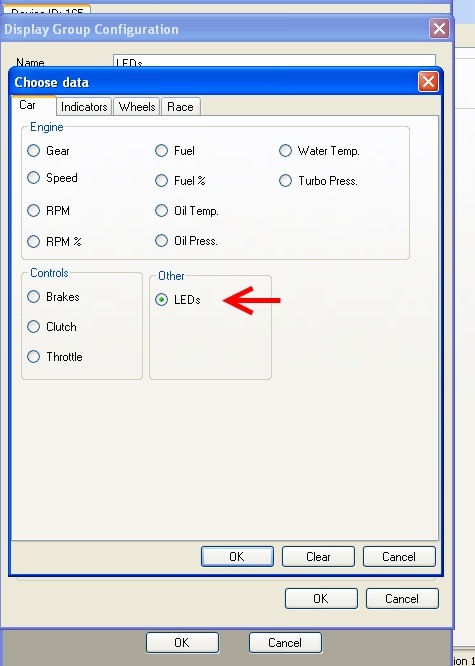
- In the Choose Data dialog select LEDs and click the OK button.
- Now the configuration screen should be like in the picture below. You can set the brightness for the group of 8 LEDs. Note that these 8 LEDs will have the same brightness level. Next step is configuring one LED as the shift light and one as the hand brake working. I decide to use LED A and LED B.
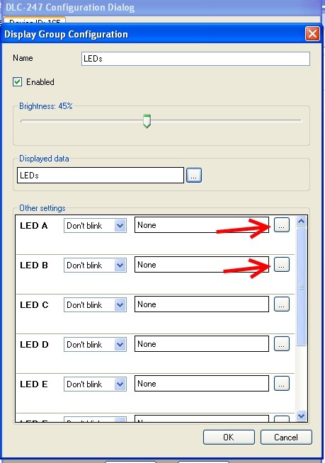
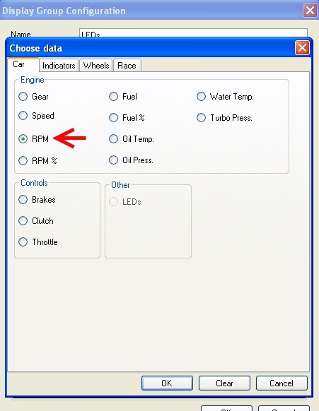
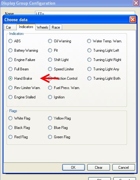
- Click the two buttons highlighted in the picture above and choose what data LED A and LED B will be associated with. Choose RPM for LED A and Hand Brake for LED B.
- Now complete the configuration on LED A setting the value of RPM at which the LED should be turned on. You can also set the blinking speed if you want. The configuration screen should be like in the picture below:
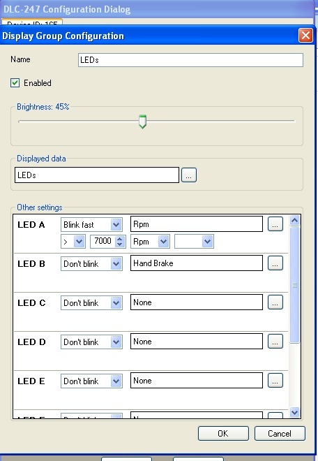
- The last step is assigning the LEDs we have just configured to Display 1.